I can report that much class time was devoted to the electrochemistry of Lithium-ion batteries. Lithium is an ideal elemental material due to its position in the upper left-hand corner of the periodic table -- in other words a very lightweight material with a potentially high energy density.
What was surprising to me was the sparseness of detailed characterization of the material properties. One instructor stated that the lack of measured diffusion properties for battery cell specifications was a pet peeve of his. Having these properties at hand allows a design engineer to better model the charging and discharging characteristics of the battery, and thus to perhaps to develop better battery management schemes. Coming from the semiconductor world, it is almost unheard of to do design without adequate device characteristics such as mobility and diffusivity.
From my perspective, this is not necessarily bad. Any time I see an anomalous behavior or missing piece, it opens the possibility I can fill a modeling niche.
Introduction
Modern rechargeable battery technology still relies on the principles of electro-chemistry and a reversible process, which hasn’t changed in fundamental terms since the first lead-acid battery came to market in the early 1900’s. What has changed is the combination of materials that make a low-cost, lightweight, and energy-efficient battery which will serve the needs of demanding applications such as electric and hybrid-electric vehicles (EV/HEV).As energy efficient operation is dependent on the properties of the materials being combined, it is well understood that characterizing the materials is important to advancing the state-of-the-art (and in increasing EV acceptance).
Of vital importance is the characterization of diffusion in the electrode materials, as that is the rate-limiting factor in determining the absolute charging and discharging speed of the material-specific battery technology. Unfortunately, because of the competitive nature of battery producers, many of the characteristics are well-guarded and treated as trade secrets. For example, it is very rare to find diffusion coefficient characteristics on commercial battery specification sheets, even though this kind of information is vital for optimizing battery management schemes [7].
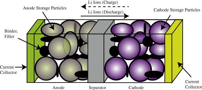
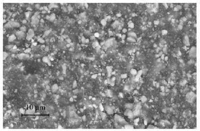
In comparison to the relatively simple diffusional mechanisms of silicon oxide growth, the engineered structure of well-designed battery cell presents a significant constraint to the diffusional behavior. In Figure 1 below we show a schematic of a single lithium-ion cell and the storage particles that charge and discharge. The disordered nature of the storage particles in Figure 2 is often described by what is referred to as a tortuosity measure.
|
|
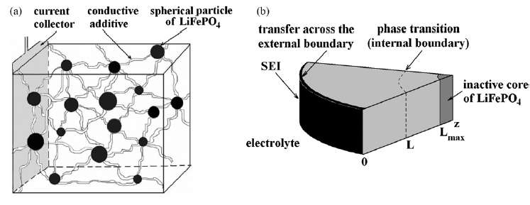 |
| Figure 3 : Diffusion of ions takes place through the radial shell of the LiFePO4 spherical particle [1]. During the discharge phase, the ions need to migrate outward through shell and through the SEI barrier before reaching the electrolyte. At this point they can contribute to current flow. |
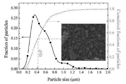 |
| Figure 4 : Particle size distribution of FeSO4F spherical granules [2]. The variation in lengths and material diffusivities opens the possibility of applying uncertainty quantification to a model of diffusive growth. |
Dispersive Diffusion Analysis of Discharging
The diffusion of ions through the volume of a spherical particle does have similarity to classical regimes such as the diffusion of silicon through silicon dioxide. That process in fact leads to the familiar Fick's law of diffusion, whereby the growing layer of oxide follows a parabolic growth law (in fact this is a square root with time, but was named parabolic by the semiconductor technology industry for historical reasons, see for example here).The model that we can use for Li+ diffusion derives from the classic solution to the Fokker-Planck equation of continuity (neglecting any field driven drift).
$$ \frac{\partial C}{\partial t} - D \nabla^2 C=0 $$ where C is a concentration and D is the diffusion coefficient. Ignoring the spherical orientation, we can just assume a solution along a one dimensional radially outward axis, x:
$$ \large C(t,x|D) = \frac{1}{\sqrt{4 \pi D t}} e^{-x^2/{4 D t}} $$
This is a marginal probability which depends on the diffusion coefficient. Since we do not know the variance of the diffusivity, we can apply a maximum entropy distribution across D.
$$ \large p_d(D) = \frac{1}{D_0} e^{-D/D_0} $$
This simplifies the representation to the following workable formulation.
$$ \large C(t,x) = \frac{1}{2 \sqrt{D_0 t}} e^{-x/{\sqrt{D_0 t}}} $$
We now have what is called a kernel solution (i.e. Green's function) that we can apply to specific sets of initial conditions and forcing functions, the latter solved via convolution.
Fully Charged Initial Conditions
Assume the spherical particle is uniformly distributed with a charge density C(0, x) at time t=0.
Discharging Model
For every point along the dimensions of the particle of size L, we calculate the time it takes to diffuse to the outer edge, where it can enter the electrolytic medium. This is simply an integral of the C(t, x) term for all points starting from x' = d to L, where d is the inner core radius.
$$ \large C(t) = \int_{d}^L C(t,L-x) dx $$
this integrates straightforwardly to this concise representation:
$$ \large C(t) = C_0 \frac{ 1 - e^{-(L-d)/{\sqrt{D_0 t}}} } {L - d} $$
The voltage of the cell is essentially the amount of charge available, so as this charge depletes, the voltage decreases in proportion.
We can test the model on two data sets corresponding to a LiPO4 cell [1] and a LiSO4F cell [2]. Figure 5 below shows the model fit for LiPO4 as the red dotted line, and which should be level-compared to the solid black line labelled 1. The other curves labelled 2,3,4,5 are alternative diffusional model approximations applied by Churikov et al that clearly do not work as well as the dispersive diffusion formulation derived above.
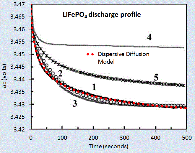 |
| Figure 5 : Discharge profile of LiFePO4 battery cell [1], with the red dotted line showing the parameterized dispersive diffusion model. The curves labelled 1 through 5 show alternative models that the authors applied to fit the data. Only the dispersive diffusion model duplicates the fast drop-off and long-time scale decline. |
Figure 6 below shows the fit to voltage characteristics of a LiSO4F cell, drawn as a red dotted line above the light gray data points. In this case the diffusional model by Delacourt shown in solid black is well outside acceptable agreement.
 |
| Figure 6 : Discharge profile of LiFeSO4F battery cell [2], with the red dotted line showing the parameterized dispersive diffusion model. The black curve shows the model that the authors applied to fit the data. |
Constant Current Discharge
Instead of assuming that the particle size is L, we can say that the L is an average and apply the same maximum entropy spread in values.
$$ \large C(t) = \int_{0}^{\infty} C(t,x) \frac{1}{L} e^{-x/L} dx $$
this integrates straightforwardly to this concise representation:
$$ \large C(t) = C_0 \frac{1}{ L + {\sqrt{D_0 t}} } $$
The reason we do this is to allow us to recursively define the change in charge to a current. In this case, to get current we need to differentiate the charge with respect to time.
$$ \large I(t) = \frac{dC(t)}{dt} $$
This differentiates to the following expression
$$ \large I(t) = - \frac{C_0}{ (L + {\sqrt{D_0 t}})^2} \frac{1}{2 \sqrt{t}} $$
But note that we can insert C(t) back in to the expression
$$ \large I(t) = \frac{C(t)}{(L + {\sqrt{D_0 t}}) 2 \sqrt{t}} $$
Finally, since I(t) is a constant and we can set that to a value of I_constant. Then the charge has the following profile
$$ C(t) = C(0) - k_c I_{constant} (L + \sqrt{Dt}) 2 \sqrt{t} $$
or as a voltage decline
$$ V(t) = V(0) - k_v I_{constant} (L + \sqrt{Dt}) 2 \sqrt{t} $$
For a set of constant current values, we can compare this formulation against experimental data for LiFePO4 (shown as gray open circles) shown in Figure 7 below. A slight constant current offset (which may arise from unspecified shunting and/or series elements) was required to allow for the curves to align proportionally. Even with that, it is clear that the dispersive diffusion formulation works better than the conventional model (solid black lines) except where the discharge is nearing completion.
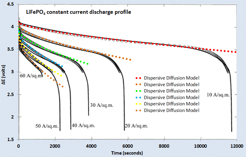 |
| Figure 7 : Constant current discharge profile [6]. Superimposed as dotted lines are the set of model fits which use the current value as a fixed parameter. |
We can also model battery charging but the lack of information on the charging profile makes the discharge behavior a simpler study.
Related Diffusion Topics
- Dispersive Transport
- Corrosive Growth
- Dispersive Flow in Fractured Wells
- Diffusive CO2 Sequestration
- Ocean Heat Content
References
[1]
A. Churikov, A. Ivanishchev, I. Ivanishcheva, V. Sycheva, N. Khasanova, and E. Antipov, “Determination of lithium diffusion coefficient in LiFePO< sub> 4 electrode by galvanostatic and potentiostatic intermittent titration techniques,” Electrochimica Acta, vol. 55, no. 8, pp. 2939–2950, 2010.
[2]
C. Delacourt, M. Ati, and J. Tarascon, “Measurement of Lithium Diffusion Coefficient in Li y FeSO4F,” Journal of The Electrochemical Society, vol. 158, no. 6, pp. A741–A749, 2011.
[3]
M. Park, X. Zhang, M. Chung, G. B. Less, and A. M. Sastry, “A review of conduction phenomena in Li-ion batteries,” Journal of Power Sources, vol. 195, no. 24, pp. 7904–7929, Dec. 2010.
[4]
J. Christensen and J. Newman, “A mathematical model for the lithium-ion negative electrode solid electrolyte interphase,” Journal of The Electrochemical Society, vol. 151, no. 11, pp. A1977–A1988, 2004.
[5]
Q. Wang, H. Li, X. Huang, and L. Chen, “Determination of chemical diffusion coefficient of lithium ion in graphitized mesocarbon microbeads with potential relaxation technique,” Journal of The Electrochemical Society, vol. 148, no. 7, pp. A737–A741, 2001.
[6]
P. M. Gomadam, J. W. Weidner, R. A. Dougal, and R. E. White, “Mathematical modeling of lithium-ion and nickel battery systems,” Journal of Power Sources, vol. 110, no. 2, pp. 267–284, 2002.
[7]
“Hybrid and Electric Vehicle Engineering Academy.” [Online]. Available: http://training.sae.org/academies/acad06/. [Accessed: 09-Jun-2013].