Context/Earth

[[ Check out my Wordpress blog Context/Earth for environmental and energy topics tied together in a semantic web framework ]]


Saturday, September 29, 2012

Bakken approaching diffusion-limited kinetics

From Great Bear Petro (image recovered 5/2/2013)


What is interesting in that GreatBear graphic is the progression of the permeability of the reservoirs. The permeability is going down by an order of magnitude for each new technology introduced. I don't understand all the intricacies of geology but I do understand the mathematics and physics of diffusion. See here.

What decreasing permeability means is that the production rates of oil are now becoming completely diffusion-limited. In other words, the flow of oil is essentially a random walk from the source to the destination. All these new technologies are doing is exploiting the capabilities of diffusion-limited capture. This is the bottom-of-the-barrel stuff, kind of like driving your car off of fumes, or keeping your maple syrup bottle upside down, to make a more intuitive analogy out of it. The Bakken rates are likely all diffusion limited and I will be willing to bet this based on some of the data from Mason.

James Mason 2012 paper

From Mason's data, the flow of oil out of a hydraulically fractured well appears to be controlled by diffusional dynamics. This is what an average Bakken well decline looks like if one uses Mason's charts.


The cumulative is the important part of the curve I believe because he plotted the instantaneous production incorrectly (which I tried to correct with the black dots).

But then if we look at Brackett's analysis of Bakken (see below), I can better fit the average well to a hyperbolic decline model. A hyperbolic decline is an ensemble average of exponential declines of different rates, assuming maximum entropy in the distribution in rates (this works to describe lots of physical phenomena).


That conflicts with the diffusional model that better describes Mason's data.

Now, I believe it's possible that Brackett simply took the 1/e decline point on each well and then tried to extrapolate that to an average production. That's the easy way out and is definitely wrong as this will always approximate a hyerbolic decline; of course I can check this if I can get access to the 3,694 samples that Brackett says goes into his analysis.

Mason and Brackett can't both be right, as there are sufficient differences between diffusional flow decline and hyperbolic decline to impact projections. The former is steeper at first but has a fatter tail, whereas the latter will definitely decline more in the long term. Brackett says the average well will generate 250,000 barrels of oil while Mason shows twice that and still increasing.

Rune Likvern has a lot of the data that he painstakingly scraped from PDF files.
Likvern 1 | Likvern 2 (in Swedish)


There will be more data forthcoming in the next few years. We will see how it pans out.

Monday, September 17, 2012

Lake ice-out dates earlier and earlier ...

With all the interest in the Arctic sea-ice extent reaching new minimums in area and volume, it seems instructive to point out a similar phenomena occurring in habitable areas.

Let's take the situation of Minnesota lakes and track the "ice-out" calendar dates.  The premise is that if the earth is warming, the ice-out dates should occur earlier and earlier in the season. A similar situation occurs for "first-ice" later in the season, but the "ice-out" date occurs very abruptly on a given day, and therefore has less uncertainty.

The time of ice-out actually occurs so suddenly on a typical lake that it takes patient observation skills to wait it out. If one is not paying attention, the ice breaks up and within a few hours it's completely melted and gone. But this abruptness is useful in terms of precision, as the timing is certain to within a day for a given lake.

Minnesota is a good test-case because it has many lakes and a hard freeze is guaranteed to occur every winter.

For this reason, "ice-out" records have a combination of qualitative knowledge and calibrated precision. The qualitative knowledge lies in the fact that it takes only one observer who knows how to read a calendar and record the date. The precision lies in the fact that the ice-out date is unambiguous, unlike other historical knowledge [1]. Since ice-out is also a natural integral averaging technique, the dates have a built-in filter associated with it and the measure is less susceptible to single-day extremes; in other words, real ice-out conditions require a number of warm days.

The data can be collected from the Minnesota DNR web site. As presented, the data has been processed and expressed in a user-friendly geo-spatial graphic showing the ice-out dates for a sampling of lakes of a given year. First, I pulled out an animated GIF below (see Figure 1 ).  If you look closely one can see a noisy drift of the tan/red/orange/yellow colors corresponding to March and early April moving northward.

Figure 1 : Animated GIF of ice-out dates in Minnesota.


Fortunately, underneath the graphics is a server that generates the processed data from a JSON-formatted data stream. By directly reading from the JSON and processing, we can come up with the linear regression plots for various geographic latitudes as shown in Figure 2. The "ice-out" day on the vertical axis is given by the number of days since the first of the year. Trying not to be too pedantic, but the lower this number, the earlier the ice-out day occurs in the year.

This essentially pulls the underlying data out of the noise and natural fluctuations. Note the trend toward earlier ice-out dates with year, and of course, a later-in-the-season ice-out day with increasing latitude. Interesting as well is the observation that greater variance in the ice-out date occurs in recent years -- in other words, the highs and lows show more extremes [2].
Figure 2: Ice-out dates for lakes of a given latitude occur earlier in the season
according to a linear regression model.

In the inset below is  logic code for retrieving and analyzing the ice-out dates from the Minnesota DNR site.  The call-out to rplot interfaces to an R package linear model plot and curve fit. My processing is two-step, first a call to get_all_records, which stores the data in memory, then a call to lat_list which retrieves the ice-out dates for a given latitude. As an example, all lake latitudes for 45N are between 45N and 46N degrees.
minnesota_dnr_ice_out('http://www.dnr.state.mn.us/services/climatology/ice_out_by_year.html?year=').

:- dynamic
    temperature/6.

assert_temperature(Name, Lat, Year, Month, Date, Days) :-
    not(temperature(Name, Lat, Year, Month, Date, Days)),
    asserta(temperature(Name, Lat, Year, Month, Date, Days)),
    !.
assert_temperature(_,_,_,_,_,_).

store_record(Term) :-
    Term=json(
             [ice_out_first_year=_IceOutFirstYear,
              ice_out_last_year=_IceOutLastYear,
              lat=Lat,
              name=Name,
              ice_out_earliest=_IceOutEarliest,
              ice_out_latest=_IceOutLatest,
              ice_out_date=IceOutDate,
              sentinel_lake=_SentinelLake,
              ice_out_number_of_entries=_IceOutNumberOfEntries,
              id=_Id,
              lon=_Lon,
              ice_out_median_since_1950=_IceOutMedianSince1950]
             ),
    atomic_list_concat([Year,Month,Date], '-', IceOutDate),
    parse_time(IceOutDate, Stamp),
    atom_concat(Year, '-01-01', YearStart),
    parse_time(YearStart, Stamp0),
    Days is (Stamp-Stamp0)/24/60/60,
    print([Name, Lat, Year, Month, Date, Days]), nl,
    assert_temperature(Name, Lat, Year, Month, Date, Days).

get_ice_out(Year) :-
    minnesota_dnr_ice_out(URL),
    atom_concat(URL, Year, U),
    http_client:http_get(U, R, []),
    atom_json_term(R, J, []),
    J=json([status='OK', results=L, message='']),
    maplist(store_record,L).

temperature_lat(Lat_Range,Year,Time) :-
    temperature(_Name,Lat,Y,_Month,_Day,Time),
    atom_number(Lat, Lat_N),
    L is floor(Lat_N),
    Lat_Range = L,
    atom_number(Y, Year).

lat_list(Lat, Years, Times, N) :-
    findall(Y, temperature_lat(Lat,Y,T), Years),
    findall(T, temperature_lat(Lat,Y,T), Times),
    format(atom(Title), '"Minnesota Latitude = ~D North"', [Lat]),
    rplot(Years,Times,Title, '"year"', '"iceOutDay"'),
    length(Years,N).


get_all_records(From, To) :-
    findall(Year, between(From, To, Year), List),
    maplist(get_ice_out, List).

According to the data, ice-out dates have gotten earlier by about a week since 1950 (and assume that via symmetry the first-ice could be a week later on average). The table below shows the slope on a per year basis, so that -0.1 would be an average 0.1 day per year earlier ice-out. Note that the slope has increased more rapidly since 1950.

LatitudeSlope since
1843
Slope since
1950
43N-0.080-0.19
44N-0.056-0.16
45N-0.099-0.15
46N-0.040-0.078
47N-0.090-0.13
48N-0.22-0.29
49N-0.25-0.25
slope in fractional days/year

The smallest decrease occurs in the center of the state where Mille Lacs Lake is located. No urban heat island effect is apparent, with a state-wide average of -0.138 days/year since 1950.

Besides this direct climate evidence, we also see more ambiguous and circumstantial evidence for warmer winters across the state -- for example we regularly see opossum in central Minnesota, which was very rare in the past.  Something is definitely changing with our climate; this last winter had a very early ice-out, showing a record for the northern part of the state.

References

[1] See the ramblings of Tony Brown, who claims qualitative data from such ambiguous sources such as interpretations of medieval and Renaissance paintings of landscapes.
[2] See J.Hansen on the New Climate Dice, and the NASA site http://www.nasa.gov/topics/earth/features/warming-links.html


Wednesday, July 4, 2012

The Bakken Dispersive Diffusion Oil Production Model


This post continues from Bakken Growth.

The Model
Intuition holds that oil production from a typical Bakken well is driven by diffusion.  The premise is that a volume of trapped oil diffuses outward along the fractures.  After the initial fracturing, oil close by the collection point will quickly diffuse through the new paths. This does not last long, however, as this oil is then replenished by oil from further away and since it takes longer to diffuse, the flow becomes correspondingly reduced. Eventually, the oil flow is based entirely on diffusing oil from the furthest points in the effective volume influenced by the original fractured zone. This shows the classic law of diminishing returns, characteristic of Fickian diffusion.

This class of problems is very straightforward to model.  The bookkeeping is that the diffusing oil has to travel various distances to reach the collection point. One integrates all of these paths and gets the production profile. I call it dispersive because the diffusion coefficient is actually smeared around a value.

One can start from the master diffusion equation, also known as the Fokker-Planck equation.
$$ \frac{\partial f(x,t)}{\partial t} = \frac{D_0}{2} \frac{\partial^2 f(x,t)}{\partial x^2} $$

Consider that a plane of oil will diffuse outward from a depth at position x. The symmetric kernel solution is given by:
$$  f(x,t) = {1\over{2\sqrt{D_0 t}}}e^{-x/\sqrt{D_0 t}} $$
If we assume that the diffusion coefficient is smeared around the value D0 with maximum entropy uncertainty, integrate from all reasonable distances from the collection point, the cumulative solution becomes

$$ P(t) =  \frac{P_0}{1+ \frac{1}{\sqrt{D t}}} $$

The reasonable distances are defined as a mean distance from the collection point and with a distribution around the mean with maximum entropy uncertainty. P0 is the effective asymptotic volume of oil collected and the diffusion coefficient turns into a spatially dimensionless effective value D. The details of the derivation are found in the text The Oil Conundrum and is what I refer to as a general dispersive growth solution; in this case the dispersive growth follows a fundamental Fickian diffusive behavior proportional to the square root of time.  This is all very basic statistical mechanics applied to a macroscopic phenomena, and the only fancy moves are in simplifying the representation through the use of maximum entropy quantification.
 

Some Data and a Model Fit
More recent data on oil production is available from an article Oil Production Potential of the North Dakota Bakken  in the Oil&Gas Journal written by James Mason.

Figure 1 below shows the averaged monthly production values from Bakken compiled by Mason. The first panel shows in blue his yearly production and his cumulative. I also plotted the dispersive diffusion model in red with two parameters, an effective diffusion coefficient and an equivalent scaled swept oil volume. Note that the model is shifted to the left compared to the blue line, indicating that the fit may be bad. But after staring at this for awhile, I discovered that Mason did not transcribe his early year numbers correctly. The panel on the bottom is the production data for the first 12 months and I moved those over as black markers on the first panel, which greatly improved the fit. The dashed cumulative is the verification as the diffusive model fits very well over the entire range.

Figure 1: Model adapted to Mason Bakken Data. Top is yearly and bottom is monthly data.

For this model, the asymptotic cumulative is set to 2.6 million barrels. This is a deceptive number since the fat-tail is largely responsible for reaching this value asymptotically. In other words, we would have to wait for an infinite amount of time to collect all the diffused oil -- such is the nature of a random walk. Even to collect 800K barrels will take 100 years from extrapolating the curve. After 30 years, the data says 550K barrels, so one can see that another 70 years will lead to only 250K barrels, should the well not get shut-in for other reasons.

If these numbers that Mason has produced are high quality, and that is a big if (considering how he screwed up the most important chart) this may become a de facto physical model describing oil production for fractured wells. I can guarantee that you won't find a better fit than this considering it is only two parameters, essentially describing a rate and a volume. This is likely the actual physical mechanism as diffusional laws are as universal as entropy and the second law.

The connection to the previous post is that the substantial production increase is simply a result of gold-rush dynamics and the acceleration of the number of new wells. Wait until these new starts stop accelerating. All the declines will start to take into effect, as one can see from the steep decline in the dispersive diffusion profiles.  We may still get returns from these wells for many years, but like the 5 barrel/day stripper wells that dot the landscape in Texas and California, they don't amount to much more than a hill of beans.  The peak oil problem has transformed into a flow problem, and unless thousands of new wells are added so that we can transiently pull from the initial production spike or to continuously pull from the lower diminishing returns, this is what Bakken has in store -- a few states with thousands and thousands of wells cranking away, providing only a fraction of the oil that we demand to keep the economy running.

If someone comes up with a way to increase diffusion, it might help increase flow, but diffusion is a sticky problem. That is what nature has laid out for us, and we may have gotten as far as we can by applying hydraulic-fracturing to lubricate the diffusion paths.

This analysis fits in perfectly with the mathematical analysis laid out in The Oil Conundrum book, and will likely get added in the next edition.


Friday, May 11, 2012

Bakken Growth

Here is the cornucopian mystery of the Bakken shale revealed. When one looks at the production of the Bakken fields, the growth seems remarkable (plotted against data from the North Dakota Dept.of Mineral Resources).
Fig 1: Bakken growth, see Fig. 3 for historical
The number of wells producing is growing at an exponential rate while the amount of oil per well is remaining high. How does that work? The total amount produced during a boom period is the convolution of the well number growth rate, N(t), and the depletion rate per well, p(t). The first term is exponentially increasing and the decline rate is exponentially decreasing, see the following chart for the latter.
Fig 2: Average decline rate
Assume that all the wells are the average decline rate for the sake of condensing the argument. $$P_T(t) = \int_0^t N(\tau) p(t-\tau) d\tau \\\\ N(t) = e^{a t} \\\\ p(t) = e^{-d t} \\\\ P_T(t) = \frac{e^{a t} - e^{-d t}}{a+d} $$ If the growth is exponential with a greater than zero, then that term will easily dominate over the declining term. Divide P(t) by N(t) and you can see that we have reached the plateau of production proportional to 1/(a+d), which you can see in the figure above. That is full bore acceleration in the number of wells coming on-line. If the growth slows to zero, then the decline kicks in and the cumulative total will start to saturate. So don't be fooled by exponential growth in well production, since as soon as the construction rate starts to slow, all of those Bakken wells will start to decline and the underlying dynamics will begin to reveal itself. That is the math story behind Gold Rush dynamics and the boom-bust cycle. Everyone gets excited because they can't see the underlying behavior.

There has been continuous extraction on the Bakken going back 50+ years to 1953.  But only with the recent boom, with hydraulic fracturing techniques, are we seeing the explosion in number of wells. The prior wells were all in serious decline I believe.

This is my plea: What we need from the Dept. of Mineral Resources of NoDak.gov is a complete set of data from every well, not the rolled up info. Even with the rolled up info, you can do some decent analysis, but why not get everything?

Fig 3 : Historical Bakken growth, first well to the left was in 1953.

For an exponential and hyperbolic decline analysis on this per county data set and note they are fairly similar in decline.
  • McKenzie has a half-life of 0.75 years
  • Williams is 1.2 years
  • Mountrail is 2.3 years
  • Dunn is 18.5 years
If they are hyperbolic declines, the total will be bigger. Dunn seems to be the only set that has any kind of sustain.


Summary of Bakken
Info Since 1/1/2007


Incremental


BOPD Wells Recovery Rec/Well Well Age Curr Ave


months BOPD


Mountrail 154,089 1,087 154,727,270 142,343 22 141.8
McKenzie 96,750 533 45,059,945 84,540 9 181.5
Dunn  75,560 613 52,446,391 85,557 22 123.3
Williams 69,513 472 30,550,213 64,725 10 147.3


Major Cos 395,911 2,705 282,783,819


Total 483,706 3,187.00 327,866,294 102,876.15 17.00 141.50


Here is a link to an Wolfram Alpha solver for exponential decline, the numbers are taken from the table above for Williams county. (The number 30 is the average days in a month, as the calculation assumes a daily production rate)

Fig. 4 : Wolfram Alpha algorithm for predicting decline rate from Rec/Well=64725, WellAge=10,CurrAveBOPD=147.3

For hyperbolic decline, example using McKenzie, rates are in per day.

Saturday, March 10, 2012

CO2 Outgassing Model (αβ)

This is one of the most interesting things I have done in a few weeks.

I am always motivated to find simple relationships that expose the seeming complexity of the climate system. In this case it involves the subtly erratic behavior observed in paleoclimate temperature versus CO2 data. The salient trends are there, in that CO2 and Temperature track each other, but the uncertainties cause climate watchers some puzzlement. The following tries to put a model-based understanding to what I think is happening. As usual, this does not rely on detailed climate models but simply pragmatic physical considerations placed in a mathematical context.

Premise. A model of long-term global temperature and CO2 interactions would assume two primary contributions.

First, we have the forcing function due to the greenhouse gas properties of atmospheric CO2 concentrations, where c = [CO2] is in parts per million (PPM). The first-order paramater alpha, α, is known as the climate sensitivity and is logarithmic with increasing concentrations (log=natural log): $$ \Delta T = \alpha \log {\frac{[CO_2]}{C_0}} $$ The second contributing factor is due to steady-state outgassing of CO2 from the ocean's waters with temperature. A first-order approximation is given by the Arrhenius rate law to estimate gaseous partial pressure. The standard statistical mechanical interpretation is the invocation of a Boltzmann activation energy to model the increase of steady-state pressure with an increasing temperature bath. $$ p = p_0 e^{\frac{-E_a}{kT}} $$ To keep things simple we use the parameter beta, β, to represent the activation energy in Kelvins, where k is Boltzmann's constant. The relation between Kelvins and electron volts is 11600 Kelvins/eV. $$ \beta = \frac{E_a}{k} $$ $$ p = p_0 e^{\frac{-\beta}{T}} $$ This works very well over a reasonable temperature range, and the activation energy Ea is anywhere between 0.2 eV to 0.35 eV. The uncertainty is mainly over the applicability of Henry's law, which relates the partial pressure to the solubility of the gas. According to a Henry's law table for common gases, the CO2 solubility activation energy is β = 2400 Kelvins. However, Takahashi et al (see reference at end) state that the steady state partial pressure of CO2 above seawater doubles with every 16 celsius degree increase in temperature. That places the activation energy around 0.3 eV or a β of 3500 Kelvins. This uncertainty is not important for the moment and it may be cleared up if I run across a definitive number.

Next, we want to find the differential change of pressure to temperature changes. This will create a limited positive feedback to the atmospheric concentration and we can try to solve for the steady-state asymptotic relationship. The differential is: $$ d[CO_2] \sim dp = \frac{\beta}{T^2} p dT \sim \frac{\beta}{T^2} [CO_2] d\Delta T $$ In terms of a temperature differential, we invert this to get $$ d\Delta T = \frac{T^2}{\beta [CO_2]} \Delta [CO_2] $$ Now we make the simple assertion that the differential changes in temperature will consist of one part of the delta change due to a GHG factor and another part due to the steady-state partial pressure. $$ d \Delta T = \frac{\alpha}{[CO_2]} d\Delta [CO_2] + \frac{T^2}{\beta [CO_2]} d\Delta [CO_2] $$ We next cast this in terms of a differential equation where dc=d[CO2] and dT = dΔT. $$ \frac{dT(c)}{dc} = \frac{\alpha}{c} + \frac{T(c)^2}{\beta c} $$ The solution to this non-linear differential equation is closed-form. $$ T(c) = \sqrt{\alpha\beta} \tan{\sqrt{\frac{\alpha}{\beta}\log{c} + K_0}} $$ The interpretation of this curve is essentially the original activation energy, β, modified by the GHG sensitivity, α. The constant K0 is used to calibrate the curve against an empirically determined data point. I will call this the αβ model.

Application. We can use the Vostok ice core data to evaluate the model. My previous posts on Vostok introduced the CO2 outgassing concept and 
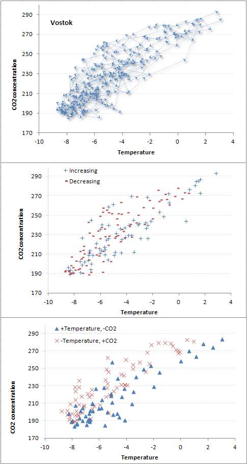
evaluated a few random walk simulations. The following figure gives an idea of the raw data we are dealing with and the kind of random walk simulation one can generate.
The key I think is to understand the seemingly random limit cycles of the atmospheric CO2 concentration with temperature. This is seen with the following graphs, reproduced from the earlier post:
The αβ model asymptote would at best draw a line through the space and couldn't explain the cloud of uncertainty (i.e. covariance) relating CO2 to Temperature.

To run a simulation,we need to establish a working temperature range, as the absolute temperature is required for the αβ model. Realizing that the actual Vostok temperature range was not known but the relative temperatures were available, I took an arbitrary starting point of 288 K (corresponding to a temperate or warm region). Some value is needed since a T^2 factor plays into the model. Placing the value 50K less will not change the interpretation.

Further, it is clear that a lag between Temperature changes and CO2 changes exists. Historically, there is little evidence that large scale CO2 changes have been the forcing function and something else (i.e. Milankovitch cycles) were assumed to kick off the climate variation. The lag is likely most noticeable on temperature decreases, as it is understood that the long adjustment time of atmospheric CO2 to sequestration is a critical and significant aspect to transient climate sensitivity.

The following figure illustrates both the steady-state αβ model and a lagged CO2 Monte Carlo simulation. The Monte Carlo random walk simulation simply integrates the d[CO2] and dΔT expressions described above, but on temperature decreases I introduce a lag by using the value of temperature from a previous step. This generates a clear lag on the trajectory through the phase space as shown in the following figure.
Another run shows a larger temperature excursion from the same starting point:
Without the introduced CO2 lag, the trajectory would simply follow the steady-state αβ curve, shown below. This is a sanity check that the Monte Carlo integration matches the analytical result as well. Note also that the following curve has a lower value of α.
If the value of α is very small, α=0.01 which corresponds to a very small GHG feedback, even with a lag then the variation of the temperature fluctuations are also reduced. The reason this happens is that the temperature acceleration due to the CO2 GHG positive feedback is reduced, and the lag has little effect on the small random walk disturbances from the steady-state values.
Finally, here is a set of 15 runs for the lagged, high-α configurations. Note that the random excursions match the empirical Vostok data remarkably well.
For the random walk, I have not introduced a reversion to the mean attractor as described in the Ornstein-Uhlenbeck post. This definitely limits the excursions to extending below the colder temperature regimes. For this set of simulations, I emulated that lower limit by assuming the initial stimulus was a positive temperature delta from the 288K starting point. The upper temperature regime is clearly limited by the Stefan-Boltzmann feedback, which is partly accommodated by the logarithmic climate sensitivity factor.

The simulations are very easy to do in a spreadsheet. I will try to create a Google Docs variation that one can interact with in this space. [I will also configure a scripted standalone simulator so that I can generate thousands of runs and accurately represent a 2D density plot -- this will more clearly show the ΔT versus [CO2] uncertainty. see below]

I am more and more convinced that paleoclimate data is the best way to demonstrate a signature of CO2 on climate change, given the paucity of long time series data from the real-time telemetry and instrumentation era (view the CO2 control knob video by Richard Alley to gain an appreciation of this). I still won't go close to applying current data for making any predictions, except to improve my understanding. Less than one hundred years of data is tough to demonstrate anything conclusively. The paleoclimate data is more fuzzy but makes up for it with the long time series.

Added 2D contour plots:


The background contour densities correspond to more probable state space occupation, assuming a start from the highest density point. Each was generated from a set of random walk simulations averaged over 1000 runs assuming an α value of 5 and a β value of 3500 Kelvins (i.e. Takahashi pCO2 doubling). The lower plot has a slightly lower β value of 3300 Kelvins and has a lag 2/3 smaller than the upper plot.

This is the simple random walk simulation source code that gets fed into gnuplot (corresponding to the lower figure).
   srand()
   RC = 0.5     ## Scale of hop
   a = 5.1      ## Alpha
   b = 3300.1   ## Beta
   f = 0.3      ## fraction of lag
   T0 = 290.9   ## start Temperature
   C0 = 226.1   ## start CO2
   loops = 1000
   while(loops--) { ## Number of runs
      T = T0
      lastT = 0.00001
      C = C0
      dT = (1.0+rand())*RC   ## Start Noise term
      dC = 0.00001
      i = 2000
      while(i--) {  ## Length of random walk sim
         dT0 = lastT
         dT1 = dT
         dC1 = dC
         dT = a*b*dT/T/T + (0.5-rand())*RC   ## Feedback+Noise
         if(dT1>0)
            dC = b*C*(f*dT+(1.0-f)*dT1)/T/T  ## Lead response
         else
            dC = b*C*(f*dT0+(1.0-f)*dT1)/T/T ## Lag response
         T += dT1
         C += dC1
         lastT = dT1
         ## Store random walk location
         Histogram[int(T),int(C)]++
      }
   }
   ## Collect statistics
   for(T=284;T<=298;T++)
      for(C=170;C<=300;C++) {
         if(Histogram[T,C]>0)
            print T ", " C ", " Histogram[T,C]
         else
            print T ", " C ", " 0
      }


References Takahashi, T; Sutherland, SC; Sweeney, C; Poisson, A; Metzl, N; Tilbrook, B; Bates, N; Wanninkhof, R; Feely, RA; Sabine, C; Olafsson, J; Nojiri, Y "Global sea-air CO2 flux based on climatological surface ocean pCO2 and seasonal biological and temperature effects" Deep-Sea Research (Part II, Topical Studies in Oceanography) [Deep-Sea Research (II Top. Stud. Oceanogr.)] 49, 9-10, pp. 1601-1622, 2002


Added per comment:

The following figure shows that Argon levels (the temperature proxy) lagging the CO2 levels .


from Caillon, et al, "Timing of Atmospheric CO2 and Antarctic Temperature Changes Across Termination III"
http://www.sciencemag.org/content/299/5613/1728.abstract


Seasonal Outgassing Model


What we also need is current data from both CO2 and sea surface temperatures (SST) to determine whether we can better calibrate the CO2 outgassing.
  • The SST data was taken from a NOMADS server (NOAA Operational Model Archive and Distribution System)
    http://nomad3.ncep.noaa.gov/cgi-bin/pdisp_sst.sh?ctlfile=monoiv2.ctl&varlist=on&psfile=on&new_window=on&ptype=ts&dir=
  • The CO2 data was taken from the Mauna Loa records, going back to 1981 to match the archival extent of the SST records
    http://www.woodfortrees.org/data/esrl-co2/from:1981
Both these sets have a monthly averaging.

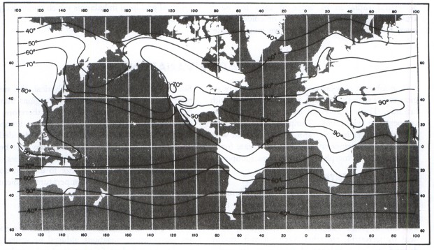
Since the Mauna Loa CO2 shows extreme sensitivity to seasonal fluctuations, I culled the SST data to give the most regional sensitivity to the maximum excursion of CO2 levels. This likely corresponds to the latitudes of maximum temperature, which should give the maximum CO2 outgassing.  From the data, the maximally warm average SST exists at around -6 degrees latitude.
January Temperatures

July Temperatures

The next step was to take a spread of latitude readings +/- 15 degrees from the maximally warm latitude. That spread is somewhat arbitrary but it captures the width of the warmest ocean regions, just south of Hawaii. See the Pacific Warm Pool.


Both the CO2 and SST curves show a sinusoidal variation with a harmonic that generates a side hump in the up-slope, as shown below. 
The harmonic also shows up in the Fourier analysis of the CO2 data, which I fit to previously.


This time, instead of doing a Fourier analysis, I used the Eureqa curve fitting tool to extract the phase information from the SST and CO2 measurements. This is very straightforward to do as one only needs to copy and paste the raw time-series data into the tool's spreadsheet entry form.

Letting the CO2 fit run in Eureqa results in this:


Letting the SST fit run in Eureqa results in this:

I chose the maximal complexity and lowest error result in both cases. Subtracting the trend and offsets from the fit, I was left with the yearly period plus one harmonic to reproduce the seasonal variations. Two periods of CO2 and SST variations are shown below:


Note how well aligned the waveforms are over the yearly cycle. The Mauna Loa measurements have a 0.04 period shift which is a mid-month reading, and I assumed the SST readings were from the beginning of each month. In any case, the lag from temperature variations to CO2 response has an uncertainty of around one month.

In the plot above, the SST readings were scaled by 3.2 to demonstrate the alignment. If we plot the phase relationship between SST and atmospheric concentrations, the transient scaling shows a slope of 3 PPM per degree C change. This is the transient outgassing relationship.


The transient outgassing is much less than the equilibrium number since the seasonal temperature variations prevent the partial CO2 concentration from reaching an equilibrium. So the [CO2] always reflects but slightly lags the current regional temperature as it tries to catch up to the continuously changing seasonal variations. This is the actual spread in the data, removing the lag:


The cross-correlation function shows alignment with 12 month cycles, which is not surprising.


So this phase plot can be compared to the phase plots for the Vostok data, which show a much larger outgassing sensitivity exaggerated by the GHG positive feedback warming mechanisms. The Vostok plot gives a 10 PPM per degree change over the interglacial temperature range.

Added:

The following figure shows two theoretical phase plots for other common soluble gases, Argon and Nitrogen. This is taken from "Continuous Measurements of Atmospheric Ar/N2 as a Tracer of Air-Sea Heat Flux: Models, Methods, and Data" by T. W. Blaine.  Note the similarity to that for CO2. The thesis is highly recommended reading as it applies many of the same math analysis, such as the two harmonic fit.


A couple of Wolfram Alpha models for the phased response of [CO2] from a forcing temperature with gain of 3, and an anthropogenic [CO2] ramp included:

First-order response: x + (1/30) dx/dt = 3*cos(2*pi*t) + 2*t

Phase relation from the solution: plot cos(2 pi t) and (675 pi sin(2 pi t)+10125 cos(2 pi t))/(15 (225+pi^2))


The value of the normalized time constant (in this case 1/30) sets the width of the slanted ellipse. The smaller that value is, the narrower the ellipse becomes.

                                     ADDED 2013                                        
Using the SST data for latitudes -6 ±15 degrees, we can take the Mauna Loa CO2 data and subtract a factor of 3 PPM/deg C  after applying a lag of 1 month. This simple transformation completely removes the seasonal oscillations, leaving only noise and perhaps a few glitches related to El Nino events (see 1998-1999).

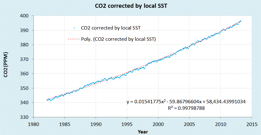
Corrected Mauna Loa CO2 data


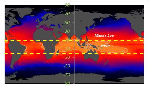
The Indo-Pacific Warm Pool (IPWP) lies within the +9N to -21S SST average

We can do the same for another CO2 reporting station in American Samoa.

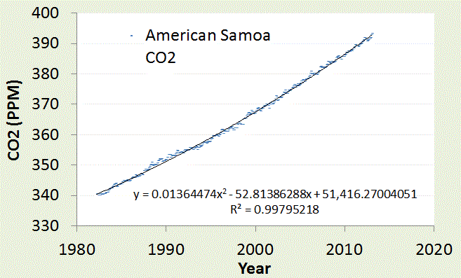
American Samoa is located in the middle of IPWP (near the label in the map).
Very little fluctuation in CO2 is observed since the temperature is seasonally stable on that latitude.


This is the carbon emission data convolved with the CO2 sequestering Green's function, sandwiched between the Mauna Loa and Samoa data. The carbon emission data is very smoothly varying after the convolution is applied so a very slight additional temperature-dependent CO2 outgassing based on filtered global SST is added.  This is slight as shown in the next graph.


If we take the residuals from the polynomial fitted curves (including one for the carbon residuals from the CDIAC, see chart above) we see how well the curves agree on a year-by-year basis.  All this really shows is that the residual is at best +/- 1 PPM which may be due to additional global SST variations (the yellow circles) but could also be any disturbances  (such as volcanic, biotic, wildfires, etc) as well as possible systemic (measurement) errors. 


Tuesday, February 21, 2012

Rainfall Variability Solved

I will preface this entry by suggesting that sometimes the statistics are so simple that they fall in your lap.

As a premise, we want to consider whether a simple stochastic model can generate statistical patterns of rainfall events.

We assume a maximum entropy probability distribution function which assumes an average energy of rainfall rate for a storm i:

$$ P(E \mid E_i) = e^{\frac{-E}{E_i}} $$

The rationale for this is that the rainfall's energy is proportional to the rate of the rainfall, since that amount of moisture had to be held aloft by gravity.

$$ Rate_i \sim E_i $$

Yet we know that the Ei can vary from storm to storm, so we leave it as a conditional, and then set that as a maximal entropy estimator as well

$$ p(E_i) = \alpha e^{- \alpha E_i} $$

then we integrate over the conditional's range.

$$ P(E) = \int_0^\infty P(E \mid E_i) p(E_i) \,dE_i $$

This results again in an integration formula lookup, which leads to the following solution:

$$ P(E) = 2 \sqrt{\frac{E}{\bar{E}}} K_1(2 \sqrt{\frac{E}{\bar{E}}})$$

where K1 is the modified BesselK function of the second kind, in this case of order 1, which is found in any spreadsheet program (such as Excel).

Note that this is the same function that we used last week for determining wind speed distributions and that we used in TOC to determine the distribution of terrain slopes for the entire planet as well!  Again this reduces to the simplest model one can imagine -- a function with only one adjustable parameter, that of the mean energy of a sampled rainfall rate measurement. In other words the expression contains a single number that represents an average rainfall rate.  That's all we need, as maximum entropy fills in the rest.

So let us see how it works.  The analysis was compared against this recent paper:
"Can a simple stochastic model generate rich patterns of rainfall events?" by S.-M.Papalexiou, D.Koutsoyiannis, and A.Montanari [2011] and graphed as shown below in Figure 1. The green points constitute the BesselK fit which lies right on top of the blue empirical data set.


Fig. 1: Cumulative rainfall distribution statistically gathered from several storm events.
The BesselK fit assumes a double stochastic process, a MaxEnt within a storm and a MaxEnt across the storms.

From the table below reproduced from the paper, we can see that the mean value used in the BesselK distribution was exactly the same as that from the standard statistical moment calculation

Event# 1 2 3 4 5 6 7 All
SampleSize 9697 4379 4211 3539 3345 3331 1034 29536
Mean(mm/h) 3.89 0.5 0.38 1.14 3.03 2.74 2.7 2.29
StandardDeviation(mm/h) 6.16 0.97 0.55 1.19 3.39 2.2 2 4.11
Skewness 4.84 9.23 5.01 2.07 3.95 1.47 0.52 6.54
Kurtosis 47.12 110.24 37.38 5.52 27.34 2.91 -0.59 91
HurstExponent 0.94 0.79 0.89 0.94 0.89 0.87 0.97 0.89

In contrast, Papalexio try to apply Hurst-Kolmogorov statistics to the problem in search of a power law solution. They claim that the power law tail of -3 is somehow significant. I would suggest instead that the slight deviation in the tail region is likely caused by insufficient sampling in the data set. A slight divergence starts to occur at the 1 part in 5,000 level and there are only 30,000 points in the merged data set, indicating that statistical fluctuations could account for the difference. See Figure 2 below which synthesizes a BesselK distribution from the same sample size, and can clearly duplicate the deviation in the tail.

Fig. 2: Monte Carlo sampling from a synthetic BesselK distribution reveals the same departure at low probability events.
Fluctuations of 1 in 30,000 are clearly seen at this level, so care must be taken to not read fat-tail behavior that may not exist.
Bottomline is that this simple stochastic model beats the other simple stochastic model, which doesn't seem as simple anymore once we apply an elementary uncertainty analysis to the data.


Added:

For the moments of the Bessel K solution, assuming the mean of 2.29, we have standard deviation of 4.00, skew of 5.01, and kurtosis of 50.35. These map fairly well to the table above. The higher moments differ because of the tail difference I believe.


Interesting if we add another composite PDF to the BesselK then we get the Meijer G function:
$$\int_0^\infty 2 K_0(2 \sqrt{y})\frac{1}{y} exp(-\frac{x}{y}) dy = G_{0,3}^{3,0}(x | 0,0,0)$$


Fig. 3: PDFs of progressively greater scaling composition. Notice the gradual fattening of the tail.


As a summary, I made an argument based on observations and intuition that rainfall buildup is a potential energy argument. This translates to a Boltzmann/Gibbs probability with a large spread in the activation energy. The large spread is modeled by maximum entropy -- we don't know what the activation energy is so we assume a mean and let the fluctuations about that mean vary to the maximum amount possible. That is the maximum entropy activation which is proportional to a mean rainfall rate -- the stronger the rate, the higher the energy That becomes the premise for my thesis, predicting the probability of a given rainfall rate within the larger ensemble defined by a mean. Scientists are always presenting theses of varying complexity. This one happens to be rather simple and straightforward. Papalexio et al, were on exactly the same track but decided to stop short of making the thesis quite this simple. They seem to imply that the PDFs can go beyond the BesselK and into the MiejerG territory, and beyond, of variability. That is fine as it will simply make it into a fatter tail distribution, and if a fatter tail matches the empirical observations on a grander ensemble scale, then that might be the natural process.

Friday, February 10, 2012

Wind speeds of the World

See if you can follow this argument for the neatest little derivation of a wind speed estimator. I believe that this thing can model the distribution of wind speeds over the entire planet.

In The Oil Conundrum, we modeled the wind speed for a single location over a span of time. This turned into a simple maximum entropy estimator, which assumed a kinetic energy for a wind volume

$$ E \sim v^2 $$

and then a probability distribution function which assumes an average energy over a region i:

$$ P(E \mid E_i) = e^{\frac{-E}{E_i}} $$

but we know that the Ei can vary from region to region, so we leave it as a conditional, and then set that as a maximal entropy estimator as well

$$ p(E_i) = \alpha e^{- \alpha E_i} $$

then we integrate over the conditional's range according to standard practice.

$$ P(E) = \int_0^\infty P(E \mid E_i) p(E_i) \,dE_i $$

This results in a simple lookup in your favorite comprehensive table of cataloged integration formulas, which leads to the following solution:

$$ P(E) = 2 \sqrt{\frac{E}{\bar{E}}} K_1(2 \sqrt{\frac{E}{\bar{E}}})$$

where K1 is the modified BesselK function of the second kind, in this case of order 1, which is found in any spreadsheet program (such as Excel).

First of all, note that this is the same function that we used in TOC to determine the distribution of terrain slopes for the entire planet as well!  There, I took a slightly different route and derived it based on a cumulative probability distribution function (CDF) instead of a probability density function (PDF). No matter, in both cases it reduces to the simplest model one can imagine -- a function with only one adjustable parameter, that of the mean energy of a sampled wind measurement. In other words the expression contains a single number that represents an average planetary wind speed.  That's all we need.

So let us see how it works.

I used wind data from Bonneville Power Administration, which has over 20 meteorological stations set up around northern Oregon. The download consisted of over 2.5 million data points collected at 5 minute intervals, archived over the span of a little less than 2 years.


Fig. 1: Cumulative distribution function of wind energies from Bonneville with model fit.
I actually didn't have to even vary the parameter, as the average energy was derived directly by computing  the mean over the complete set of data separately. This corresponded to a value of 12.4 MPH, and I placed a pair of positive and negative tolerances to give an idea of the sensitivity of the fit.

As this is a single parameter model, the only leeway we have is in shifting the curve horizontally along the energy axis, and since this is locked by an average, the fit becomes essentially automatic with no room for argument. The probabilities are automatically normalized.

I also show the log-log plot next, which reveals a departure at high wind speeds.

Fig. 2: Cumulative distribution function of wind energies on a log-log plot.
At large wind speeds, the fit diverges from the data as the peak 5-minute wind speed observed was 60 MPH.

I am not too worried about this slight divergence as it only shows that excessive gale force winds (greater than 60 MPH) did not occur over the extended region during a span of two years.  The next logical step is to average this over longer times and larger spatial regions.


I have to admit that this investigation into the Bonneville dataset was prompted by a provocation and a dare on another blog.  In my opinion, anti-renewable-energy advocates seem to crawl out of the woodwork, and tend to spread their misery however they can. This commenter was named P.E. (possibly the professional engineer moniker), and what set me off was his assertion that wind "power output is essentially random":
  • I did a little research on the Bonneville system a year or so ago, because they have all their SCADA data available for several years online with excellent resolution. The results were downright shocking. And not in a good way. And this is real live system-wide data, not modeled results. Anyway, be sure to check Bonneville’s website out; it’s low hanging fruit.
    Bonneville’s own words: “power output is essentially random”.
  • Predictability is not the issue. Even if we knew just when the wind would not blow (about 70% of the time) we would still have to have a fueled power plant to produce the needed power, either that or some humongous expensive power storage systems. Renewables reduce emissions by idling existing fueled power plants. That is the most they can do. They are not an alternative to fueled power plants.
  • P.E. 
    In the specific case of Bonneville, they have enough hydro in the system to where reserve/backup isn’t an issue. The windmills allow them to use less water when it’s available, making more hydro power available when it’s needed. That’s the ideal situation for wind (and solar). But not that many places in the world can do that.
  • PE, You are so full of it as to be embarrassing. I have done statistical analysis of wind energy and it follows maximum entropy principles. You can read all about it and more to come, as I seem to have the knack for environmental modeling. Too bad you missed the boat on this one.
  • P.E.
    Web, go do the analysis yourself, and then come back after you’ve looked at some real data. They seem to have changed their web site around, but here’s a place to start: http://www.intellectualtakeout.org/library/chart-graph/load-and-wind-generation-are-essentially-random?library_node=69696
    And this: http://pjmedia.com/blog/electric-grid-myths-part-ii-the-effect-of-alternatives/
    There used to be some huge excel spreadsheets as evidenced by the two articles above (that my computer would choke on), but they’re either moved to another part of the site, or no longer available to the public.
    Maybe I’ll do a FOIA. :twisted:
  • P.E.
    Correction: they’re right here:
    http://transmission.bpa.gov/Business/Operations/Wind/default.aspx
    Item #5. Now go to work, or eat your words.
  • P.E.
    Oh, and Web – if you need any help with Excel, I hear Phil Jones is really good at it.
  • P.E., That’s the problem with your ilk. You are basically ashamed about not being able to do the analysis yourself so lash out at someone like me that knows something about probability and statistics. It is all pathetic, this transparently petty jealousy.
  • hunter 
    WHT, who do we believe? Someone who cites a third party that is actually running a windfarm, or a self declared genius like you who has not bothered to challenge the citation, but blames the person who referred to it?
  • Hunter, The problem is that he shows a spreadsheet with raw data of a few weeks. I have analyzed data from wind farms, compiling the data over the span of a year in terms of a probability distribution. I have it right here on my blog
    http://mobjectivist.blogspot.com/2010/05/wind-energy-dispersion-analysis.html

    And it is also in my recent book which you can click on my handle to read for free.
    You have to keep up with renewable research, otherwise you will be left behind.
  • hunter
    Web, wind is crap , delivering z small fraction of its rated capacity.
  • P.E. 
    For the record, that’s not a few weeks, that’s five years. And just for the edification of the ignorant, Bonneville Power Authority is the largest federal hydropower agency in the US, including the Grand Coulee dam at something like 7 gigawatts. This isn’t some small-potatoes outfit.
    But keep kvetching.
  • Kiddies all jealous over the fact that I know how to do the analysis.
The larger point is that the randomness can be modeled, which the garden-variety dogmatists don't seem to understand. This is really no different than understanding black-body Planck's response for radiative emission. Sure, the radiation appears random, but it also must still follow a distribution function with respect to wave-number, which is proportional to energy and thus follows statistical mechanical laws.  The same thing holds for wind energy distributions, and we are seeing statistical mechanics, superstatistics, and maximum entropy principles hold sway. 

Bottomline is that these environmental skeptics are renowned for all talk and no action when it comes to discussing energy and climate. I admit that I was needling the guy, but that's what prompts them to spill their true agenda, which is hatred against climate scientists coupled with a strange mix of Malthusian, Luddite, and Cornucopian ideals. They actually lash out angrily when they see somebody trying to scientifically advance the yardstick.

A few days later and in another thread, P.E. wouldn't let go, and went out on a limb:
  • This scold coming from someone who refuses to download wind data from the Bonneville Power Authority because it’s too much like work.
  • What a wanker, P.E.
    I downloaded data from Ontario and Germany wind farms about a year and a half ago and did a comprehensive analysis of the time series data. I happen to be on vacation over the holiday, so am not going to bend over backwards to work the Bonneville data at your whim and call.
    I tell you what; I will analyze the Bonneville data set when I get back, and I will add it to a future revision of my tome.
    But then again, maybe not, because trained seal and organ-grinder monkey is not my forte.
As in Judo, we learn to use our opponents force and redirect it back at them. They have no intellectual curiosity, and think that just by asserting something it must be true.  Only by applying models to empirical data can we make headway in our understanding of our environment.  The last laugh is on P.E. and I have to thank him for providing motivation to do this analysis.


The pushback I see against this model from the skeptical trenches is that it doesn't predict chaotic disturbances. I view chaotic bifurcation as a no-nothing theory. We can't predict anything using it, but know that an external forcing will always overpower the minor chaotic fluctuations that may occur. In other words, chaos is annoying noise in the bigger scheme of things.

The only caveat is whether that noise will also scale with the external forcing -- in other words the fluctuations growing bigger with added heat to the system. This is understood with respect to added heat raising the kinetic energy of the system - (1) increasing the average atmospheric wind speed, and (2) added heat to the ocean allowing for greater occasional releases into the atmosphere. These are likely subtle effects, but they will only go in that direction. Remember, reducing heat leads to lower thermal excitation.

The BesselK wind model has a thermal excitation built-in, as the maximum entropy estimator for average energy is nothing but a thermalized Boltzmann partition function describing the system's entropy.

Entropy measures the thermal excitation of the system and that scales with temperature. Non-linearities and chaos is just a way for the disordered system to explore the ergodic range of states, thus making the statistical mechanical/information theory valid. Look at how a naive pseudo-random number generator is created -- by sticking a handful of non-linear functions together, you will explore the state space (see the topic of iterated maps). Voila, it will approach an ergodic limit. Then add in energy constraints, such as the mean energy of the system and you have the Boltzmann estimator, aka MaxEnt estimation.


See also the topic of K-distribution model which models the disorder, or clutter, in electromagnetic interference. This also uses the BesselK model.


Another interesting observation. In the semiconductor world, the transport regimes analogous to the stochastic and chaotic/deterministic talked about in climate circles are diffusive and ballistic transport. It is very hard to get to ballistic transport because the carriers thermalize so rapidly, which is the essential dissipation route to diffusive transport. The idea of stochastic resonance is all over the place in semiconductor physics and technology, with carrier population inversions, bandgap engineering, etc. but we don't talk about it as stochastic resonance because there is already a well established terminology.

On top of that, there is the concept of dispersive transport, which is diffusive transport with huge amounts of disorder in the mobilities and bandgaps. This is the concept that I have done some recent research on because all the cheap photovoltaic technology is built on amorphous or polycrystalline garbage.

On that level, what I think is happening in the climate system is closer to a mix of dispersion and diffusion than determinism.

For example, relating to wind speed distribution, we need to get a handle on what controls the dispersion. From other posts that I have done on wind speed, remembered that the wind power dissipation is the cube of the wind speed, while the distribution that has a skew (the third statistical moment) equal to the mean is just the BesselK distribution that matches the empirical results. This is to me is somewhat mysterious ... is it just that the mean wind speed matches statistically the dissipation due to friction? Could that be some universal scaling result? In terms of maximum entropy it would be the distribution that has a constraint of a finite mean with the mean equating to cube root of the third moment (i.e Mean = standardDeviation * Skew). This then determines all the fluctuations observed over the larger ensemble.